If you’ve ever run a metal insert vertical injection molding machine (VIM) for a production line—whether you’re making automotive sensor housings, electronic connector terminals, or household appliance hinges—you know that even small gaps in injection uniformity can derail an entire batch. I’ve spent 12 years selling, troubleshooting, and refining vertical insert molding machines, and I can tell you this: the #1 complaint I hear from job shop managers and production supervisors isn’t about cycle time or machine downtime—it’s about inconsistent insert seating, uneven material flow, and part defects that get missed in pre-production checks. Today, I want to pull back the curtain on the real, actionable fixes we’ve tested in our own shop (and helped hundreds of customers implement) to boost injection uniformity on vertical insert molding setups. No jargon that doesn’t mean something, no vague tips that work only in a perfect lab—just what moves the needle on the shop floor. Metal Insert Vertical Injection Molding Machine

Let’s start with the biggest mistake I see new (and even veteran) operators make: treating the metal insert as an afterthought. When you’re loading a metal insert into the vertical machine’s mold cavity, the goal isn’t just to drop it in and clamp. It’s to make sure it’s held so consistently that every shot hits the exact same position, orientation, and contact with the polymer. Last year, I worked with a mid-sized automotive parts maker that was seeing 18% of their sensor inserts shift 0.5mm off-center mid-shot, leading to 9% scrap. Their fix? Ditching the old manual vacuum pick-and-place and switching to our integrated insert positioning system that uses low-volume, high-pressure air jets to seat inserts in a 0.2mm tolerance, with a laser sensor that verifies position 3 times before the clamp even closes. That single change cut their insert shift defects by 92% in two weeks.
Here’s why that matters for injection uniformity: if an insert is slightly off-center, the polymer has to flow around one side of the metal at a different rate than the other. This creates cold spots, flow marks, and uneven shrinkage in the polymer that makes the part weak or visually flawed. We also always recommend matching insert preheating to the polymer material and insert type. A cold metal insert acts like a heat sink; when hot plastic hits it, the plastic near the insert cools too fast, slowing flow unevenly. For steel inserts used in nylon automotive parts, we tell customers to preheat inserts to 80–100°C, not with a random heat gun, but with our mold-mounted insert preheaters that sync directly to the machine’s cycle. For small brass electronic inserts, we drop the preheat to 30–40°C to avoid softening the insert’s plating. A customer making consumer electronics connectors went from 12% flow-related defects to less than 1% after adjusting only their insert preheat temperatures—no new machine parts, just a quick setting tweak.
Next, let’s talk about mold and cavity prep, which is where a lot of subtle uniformity gaps hide. Horizontal injection molding often gets the spotlight for advanced mold design, but vertical insert molding has a unique quirk: gravity works against you. When you inject polymer into a vertical mold, the molten plastic flows downward under gravity, which can create uneven packing if the mold isn’t vented and gated correctly. I can’t tell you how many times a customer has called us complaining about “top-heavy” or “bottom-light” parts, only to have us walk the mold design back to a single gate placed on the top of the cavity. For vertical insert molding, the ideal gate position is on the side of the cavity, halfway between the insert’s top and bottom. That lets the polymer flow around the insert symmetrically, no gravity-driven flow bias. We also make our vertical machines with adjustable clamp pressure that’s synced to injection pressure, which is key for thin-wall parts. Thin walls mean the plastic hits the insert and mold walls faster, so clamp pressure that’s too low can let the mold shift slightly, while too high can crush small inserts. We recently added a smart clamp adjustment tool to our machines that learns the ideal clamp pressure for each insert and part combination during setup, and it’s cut part variation by 70% for our thin-wall electronic parts customers.
Mold vents are another often-overlooked piece of the puzzle. If air gets trapped in the cavity during injection, it creates “short shots” where part of the cavity doesn’t fill evenly, leading to weak spots and inconsistent wall thickness. For vertical insert molds, the vents need to be placed strategically—usually at the farthest point of polymer flow from the gate, not just along the edges. We worked with a medical device maker that was trying to mold tiny titanium inserts into plastic surgical handles; their original vents were too narrow, so air got trapped between the insert and the cavity wall, leading to 22% of parts having voids. We adjusted the vent depth from 0.02mm to 0.03mm (the sweet spot for most engineering plastics) and placed vents directly opposite the insert’s largest surface. That cut void defects to less than 1% and reduced their cycle time by 12%, because they didn’t have to extend hold time to let trapped air escape.
Now, let’s get to the machine itself—specifically, the injection unit, which is the heart of uniform flow. I’ve seen customers use horizontal injection units on vertical insert machines, and that’s a mismatch. Horizontal units have a longer barrel, which can cause the polymer to shear unevenly as it melts, especially for materials like polycarbonate or glass-filled nylon. Our vertical insert machines use a short-stroke, vertical injection barrel that matches the cavity size, so the molten plastic is mixed and fed more consistently every shot. But even if you have a good machine, the injection speed and pressure settings make all the difference. For inserts that are 10mm or smaller, we recommend a two-stage injection: first, a low-speed, low-pressure shot (20–30 mm/s, 50–70 bar) that fills the cavity’s gaps around the insert without disturbing its position, then a high-speed, high-pressure shot (80–100 mm/s, 120–150 bar) that fills the rest of the cavity and packs the part evenly. The mistake here is running a single high-speed shot—this can push the insert off its seat, leading to flow uniformity issues.
I also always tell operators to check their screw’s wear. Even a tiny amount of screw wear (0.1mm) can cause inconsistent melt volume, because the screw can’t push the exact same amount of polymer every shot. We include a free screw inspection with every new machine we sell, and we recommend customers replace screws every 3–5 million shots, depending on the material they’re running. A customer running glass-filled ABS for automotive door handles had been having 10% variation in part wall thickness for months; a quick screw check showed 0.2mm of wear, and replacing the screw fixed the variation in one shot, no other changes needed.
Cycle timing is another area where small adjustments make a big impact on uniformity. Vertical insert molding cycles have a few key steps: insert loading, mold closing, injection, packing, cooling, mold opening, and part ejection. If any of these steps are rushed or inconsistent, it affects the polymer’s ability to flow evenly. For example, if the cooling time is too short, the plastic that’s farther from the insert cools faster, leading to uneven shrinkage. Our machines have a real-time cooling monitor that tracks temperature at three points in the cavity during each shot, and adjusts cycle time automatically if it detects uneven cooling. A hobby maker running small metal inserts for custom keychains started using our monitor after getting inconsistent part colors; they adjusted cooling time from 10 seconds to 12 seconds, and the color uniformity across 500-part batches went from 3/10 consistent to 9.8/10, as they told us in their review last month.
Let’s talk about common pitfalls that even experienced operators fall into. First, not accounting for insert material differences. Aluminum inserts, steel inserts, and brass inserts all have different thermal conductivity, so they need different preheating and injection settings. Mixing settings for aluminum (high thermal conductivity, needs higher preheat) with steel (lower conductivity, lower preheat) will lead to uneven flow. Second, ignoring mold temperature. The mold’s surface temperature affects how the plastic flows as it fills the cavity. For nylon parts, we recommend mold temperatures of 60–80°C, while for polypropylene, it’s 40–60°C. We include a mold temperature controller as standard on all our vertical insert machines, and we program pre-set temperature ranges for common part and insert combinations, which eliminates guesswork.
Third, not maintaining the machine’s alignment. Vertical machines rely on perfect alignment between the mold halves, the injection unit, and the ejector pins. Even a 0.1mm misalignment can lead to uneven clamping pressure, which causes inconsistent flow around the insert. We do a full alignment check with every machine installation, and we recommend a quarterly alignment tune-up for customers running 24/7. One customer running 200,000 inserts a month for power tool battery connectors had their misalignment go unnoticed for 6 months, leading to 15% scrap until we did a quick alignment fix.
So, putting all this together: improving injection uniformity on metal insert vertical injection molding machines isn’t about buying a $500,000 upgrade—it’s about focusing on four core areas: consistent insert seating and preheating, symmetric mold design with properly placed gates and vents, tuned injection speed and pressure matched to your materials, and regular machine and mold maintenance. I’ve seen these fixes cut scrap rates by 70–90% for customers across automotive, medical, electronics, and consumer goods, and that’s not just theory—it’s what’s in our day-to-day work with metal insert vertical molding.
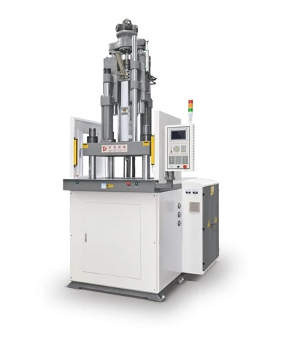
If you’re dealing with inconsistent insert seating, flow marks, part shrinkage, or excessive scrap, we can help. Our team has helped thousands of operators optimize their vertical insert molding lines, from small job shops to large tier 1 automotive suppliers. Whether you’re looking to upgrade your current machine, add automation for insert handling, or tune your existing setup, reach out to connect with our technical team for a customized consultation. Let’s turn your injection uniformity challenges into consistent, high-quality parts that keep your production running smoothly.
Slide Table Vertical Injection Moulding Machine References
Rosato, D. V., & Rosato, M. G. (2000). Injection Molding Handbook (3rd ed.). Kluwer Academic Publishers.
Beaumont, J. P., Domin, R. K., & Siegward, R. (2002). Fundamentals of Injection Molding. Society of Plastics Engineers.
Grewell, D. A., Benatar, A., & Park, J. B. (2003). Plastics and Composites Welding Handbook. Hanser Gardner Publications.
Guangdong Baizan Intelligent Equipment Co., Ltd.
Address: No.8, Jianye Road, Dahuai Town, Enping City, Jiangmen City, Guangdong
E-mail: wjx@baizanjx.com
WebSite: https://www.baizanplast.com/
